[ RETURN TO ALL WORK ]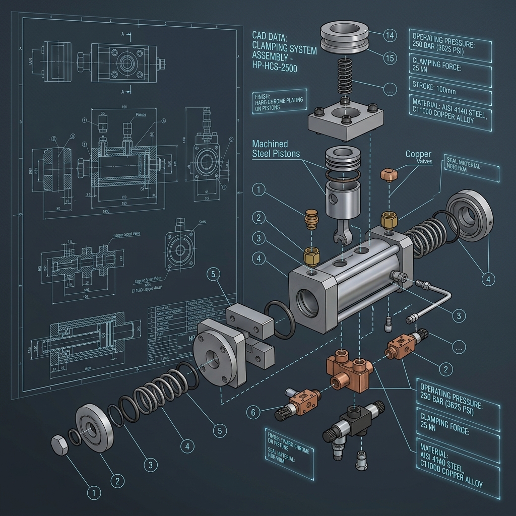
[ CASE SPECIFICATION // CAD / 3D Modeling ]
High-Pressure Hydraulic Clamping System.
Designed an ultra-compact 350-bar hydraulic workholding clamping system for high-volume automotive transmission housing machining. Features internal oil channels drilled directly into monolithic steel block manifolds to eliminate external hydraulic hoses.
SolidWorks MBDAutoCAD FluidHydraulic SimulationGD&T
01 // ISOMETRIC 3D CAD RENDER
01 // TECHNICAL CHALLENGE
External hydraulic hoses were vulnerable to flying CNC aluminum chips, causing fluid leaks and fixture reload downtime every few days.
02 // ENGINEERING & DFM SOLUTION
Engineered gun-drilled gunmetal internal fluid passages inside a heat-treated 4140 steel manifold block, incorporating quad-ring seals and micro-inductive sensors.
03 // MODELING & TOLERANCING HIGHLIGHTS
—Complex gun-drilling clearance verification using SolidWorks Intersect tool
—3D Model-Based Definition (MBD) step files with native Y14.41 annotations
—Dynamic motion assembly simulation with hydraulic fluid velocity checks
TECHNICAL SPECIFICATIONS
Operating Pressure:350 Bar (5,076 PSI)
Clamping Force:42 kN per cylinder
Stroke Length:25 mm Precision Stroke
Repeatability:±0.003 mm
Manifold Material:AISI 4140 Nitrided Alloy Steel
QUANTITATIVE RESULTS
✓100% elimination of external hose failure points
✓Cycle time per part reduced by 18 seconds due to rapid dual-stage clamping
✓Maintained micro-micron positioning accuracy over 500,000 actuation cycles
“
Haris's hose-less manifold design eliminated our #1 source of CNC line stoppage. Precision engineering at its absolute finest.
David Chen — Director of Tooling & Automation, PrecisionMach Global